Attention
Reproduce
This section of the User Guide describes how to reproduce a standard EWAOL distribution image for a supported target platform, configuring and deploying the supported set of distribution image features, and running simple examples of the EWAOL Use-Cases.
Introduction
The recommended approach for image build setup and customization is to use the kas build tool. To support this, EWAOL provides configuration files to setup and build different target images, different distribution image features, and set associated parameter configurations.
This page first briefly describes below the kas configuration files provided with EWAOL, before guidance is given on using those kas configuration files to set up the EWAOL distribution on a target platform.
Note
All command examples on this page can be copied by clicking the copy button. Any console prompts at the start of each line, comments, or empty lines will be automatically excluded from the copied text.
The meta-ewaol-config/kas directory contains kas configuration files to
support building and customizing EWAOL distribution images via kas. These kas
configuration files contain default parameter settings for an EWAOL distribution
build, and are described in more detail in
Build System. Here, the files are
briefly introduced, classified into three ordered categories:
Architecture Configs: Set the target EWAOL architecture
baremetal.ymlto prepare an image for the baremetal architecture.
virtualization.ymlto prepare an image for the virtualization architecture.Build Modifier Configs: Set and configure features of the EWAOL distribution
tests.ymlto include run-time validation tests on the image.
baremetal-sdk.ymlto build an SDK image for the baremetal architecture.
virtualization-sdk.ymlto build an SDK image for the virtualization architecture.
security.ymlto build a security-hardened EWAOL distribution image.
xen_pci_passthrough.ymlto include the necessary configuration to enable support for Xen Guest VM PCI passthrough. The configuration provided in this Build Modifier Config will only take effect when building an EWAOL virtualization distribution image, and is currently only supported on the AVA Developer Platform.Target Platform Configs: Set the target platform
EWAOL currently supports two hardware target platforms, each with its own Target Platform Config:
n1sdp.ymlto select the Neoverse N1 System Development Platform (N1SDP) as the target platform, corresponding to then1sdpMACHINEimplemented in meta-arm-bsp.See N1SDP Technical Reference Manual for more details about the N1SDP.
ava.ymlto select the AVA Developer Platform (AVA) as the target platform, corresponding to theavaMACHINEimplemented in meta-adlink-ampere.See AVA Developer Platform for more details about AVA.
Note
Additional information on EWAOL features such as run-time validation tests and the SDK can be found in the Developer Manual
These kas configuration files can be used to build a custom EWAOL distribution by passing one Architecture Config, zero or more Build Modifier Configs, and one Target Platform Config to the kas build tool, chained via a colon (:) character. Examples for this are given later in this document.
In the next section, guidance is provided for configuring, building and deploying EWAOL distributions using these kas configuration files.
Build Host Environment Setup
This documentation assumes an Ubuntu-based Build Host, where the build steps have been validated on the Ubuntu 18.04.6 LTS Linux distribution.
A number of package dependencies must be installed on the Build Host to run build scenarios via the Yocto Project. The Yocto Project documentation provides the list of essential packages together with a command for their installation.
The recommended approach for building EWAOL is to use the kas build tool. To install kas:
sudo -H pip3 install --upgrade kas==3.1
For more details on kas installation, see kas Dependencies & installation.
To deploy an EWAOL distribution image onto the supported target platform, this
User Guide uses bmap-tools. This can be installed via:
sudo apt install bmap-tools
Note
The Build Host should have at least 65 GBytes of free disk space to build an EWAOL baremetal distribution image, or at least 100 GBytes of free disk space to build an EWAOL virtualization distribution image.
Download
The meta-ewaol repository can be downloaded using Git, via:
# Change the tag or branch to be fetched by replacing the value supplied to
# the --branch parameter option

mkdir -p ~/ewaol
cd ~/ewaol
git clone https://gitlab.com/soafee/ewaol/meta-ewaol.git --branch kirkstone-dev
cd meta-ewaol
Build
The provided kas configuration files can be combined to build and EWAOL distribution image for different target platforms, for different EWAOL system architectures, and to apply different sets of customizable parameters. Therefore, the following build guidance is provided as a set of alternatives to target each of the main supported use cases.
Alternatives are distinguished first by EWAOL system architecture as distinct sections, then by hardware target platform or distribution image feature, with each alternative denoted alphabetically (e.g., A, B, …).
Baremetal Distribution
To build a baremetal distribution image:
For the N1SDP hardware target platform:
kas build --update meta-ewaol-config/kas/baremetal.yml:meta-ewaol-config/kas/n1sdp.ymlThe resulting baremetal distribution image will be produced at:
build/tmp_baremetal/deploy/images/n1sdp/ewaol-baremetal-image-n1sdp.*
For the AVA hardware target platform:
kas build --update meta-ewaol-config/kas/baremetal.yml:meta-ewaol-config/kas/ava.ymlThe resulting baremetal distribution image will be produced at:
build/tmp_baremetal/deploy/images/ava/ewaol-baremetal-image-ava.*
To build a baremetal distribution image with the EWAOL SDK:
For the N1SDP hardware target platform:
kas build --update meta-ewaol-config/kas/baremetal-sdk.yml:meta-ewaol-config/kas/n1sdp.ymlThe resulting baremetal distribution image which includes the EWAOL SDK will be produced at:
build/tmp_baremetal/deploy/images/n1sdp/ewaol-baremetal-sdk-image-n1sdp.*
For the AVA hardware target platform:
kas build --update meta-ewaol-config/kas/baremetal-sdk.yml:meta-ewaol-config/kas/ava.ymlThe resulting baremetal distribution image which includes the EWAOL SDK will be produced at:
build/tmp_baremetal/deploy/images/ava/ewaol-baremetal-sdk-image-ava.*
EWAOL baremetal distribution images can be modified by adding run-time
validation tests and security hardening to the distribution. This can be done
by including meta-ewaol-config/kas/tests.yml and
meta-ewaol-config/kas/security.yml kas configuration file as a Build
Modifier.
See Run-Time Integration Tests for more details on
including run-time validation tests and
Security Hardening for more details on security
hardening.
Virtualization Distribution
To build a virtualization distribution image:
For the N1SDP hardware target platform:
kas build --update meta-ewaol-config/kas/virtualization.yml:meta-ewaol-config/kas/n1sdp.ymlThe resulting virtualization distribution image will be produced:
build/tmp_virtualization/deploy/images/n1sdp/ewaol-virtualization-image-n1sdp.*
For the AVA hardware target platform:
kas build --update meta-ewaol-config/kas/virtualization.yml:meta-ewaol-config/kas/ava.ymlThe resulting virtualization distribution image will be produced:
build/tmp_virtualization/deploy/images/ava/ewaol-virtualization-image-ava.*
To build a virtualization distribution image with the EWAOL SDK:
For the N1SDP hardware target platform:
kas build --update meta-ewaol-config/kas/virtualization-sdk.yml:meta-ewaol-config/kas/n1sdp.ymlThe resulting virtualization distribution image which includes the EWAOL SDK will be produced at:
build/tmp_virtualization/deploy/images/n1sdp/ewaol-virtualization-sdk-image-n1sdp.*
For the AVA hardware target platform:
kas build --update meta-ewaol-config/kas/virtualization-sdk.yml:meta-ewaol-config/kas/ava.ymlThe resulting virtualization distribution image which includes the EWAOL SDK will be produced at:
build/tmp_virtualization/deploy/images/ava/ewaol-virtualization-sdk-image-ava.*
As with the EWAOL baremetal guidance above, EWAOL virtualization distribution
images can also be modified to include run-time validation tests and security
hardening by adding meta-ewaol-config/kas/tests.yml and
meta-ewaol-config/kas/security.yml kas configuration files respectively. In
addition, an EWAOL virtualization distribution image built for the AVA Developer
Platform can be customized so that Guest VMs may be assigned an exclusive PCI
device via Xen PCI passthrough capability, added via the
meta-ewaol-config/kas/xen_pci_passthrough.yml kas configuration file.
See Run-Time Integration Tests for more details on
including run-time validation tests,
Security Hardening for more details on security
hardening, and Configuring Guest VM PCI Device Passthrough for more details on
PCI passthrough configuration.
Customization
EWAOL defines a set of standard customizable environment variables for
configuring the VMs included on a virtualization distribution image. The
following list shows the variables and their default values (where MB and
KB refer to Megabytes and Kilobytes, respectively), when including one Guest
VM instance:
EWAOL_GUEST_VM_INSTANCES: "1"                      # Number of Guest VM instances
EWAOL_GUEST_VM1_NUMBER_OF_CPUS: "4"                # Number of CPUs for Guest VM1
EWAOL_GUEST_VM1_MEMORY_SIZE: "6144"                # Memory size for Guest VM1 (MB)
EWAOL_GUEST_VM1_ROOTFS_EXTRA_SPACE: ""             # Extra storage space for Guest VM1 (KB)
EWAOL_CONTROL_VM_MEMORY_SIZE: "2048"               # Memory size for Control VM (MB)
EWAOL_CONTROL_VM_ROOTFS_EXTRA_SPACE: "0"           # Extra storage space for Control VM (KB), added as additional space above the storage necessary to support all Guest VMs root filesystems
To customize these standard variables, set their value in the environment for the kas build. For example, to build a virtualization distribution image for the N1SDP using the above default values, but allocating a non-default value of eight CPUs for its Guest VM, run:
EWAOL_GUEST_VM1_NUMBER_OF_CPUS=8 kas build --update meta-ewaol-config/kas/virtualization.yml:meta-ewaol-config/kas/n1sdp.yml
An additional non-default environment variable is available for each Guest VM, which can be used to assign the Guest VM exclusive use of a single PCI device. Using this environment variable requires that the Xen PCI passthrough capability is enabled. Details for enabling this capability is provided at Configuring Guest VM PCI Device Passthrough. This will provide a corresponding environment variable for each Guest VM, such as the following variable and its default value for the first Guest VM:
EWAOL_GUEST_VM1_PCI_PASSTHROUGH_DEVICE: "0000:01:00.0" # PCI device ID to be assigned
EWAOL supports adding multiple independently-configurable Guest VMs to a virtualization distribution image. Additional details for this are provided at Customization.
Deploy
This section provides instructions for deploying an EWAOL distribution image on the support hardware target platforms:
Note
As the image filenames vary depending on the architecture and the inclusion of the SDK, the precise commands to deploy an EWAOL distribution image vary. The following documentation denotes required instructions with sequentially numbered indexes (e.g., 1, 2, …), and distinguishes alternative instructions by denoting the alternatives alphabetically (e.g., A, B, …).
The deployment guidance requires a physical connection able to be established between the hardware target platform and a PC that can be used to interface with it. For simplicity, this PC is assumed to be the Build Host.
N1SDP
Instructions for deploying an EWAOL distribution image on the N1SDP hardware target platform are divided into two parts:
Load the Image onto a USB Storage Device
EWAOL distribution images are produced as files with the .wic.bmap and
.wic.gz extensions. They must first be loaded to a USB storage device, as
follows:
Prepare a USB storage device (minimum size of 64 GB).
Identify the USB storage device using
lsblkcommand:lsblkThis will output, for example:
NAME   MAJ:MIN RM   SIZE RO TYPE MOUNTPOINT
sdc      8:0    0    64G  0 disk
...
Warning
In this example, the USB storage device is the /dev/sdc device. As this
may vary on different machines, care should be taken when copying and pasting
the following commands.
Prepare for the image copy:
Baremetal
sudo umount /dev/sdc*
cd build/tmp_baremetal/deploy/images/n1sdp/
Virtualization
sudo umount /dev/sdc*
cd build/tmp_virtualization/deploy/images/n1sdp/
Warning
The next step will result in all prior partitions and data on the USB storage device being erased. Please backup before continuing.
Flash the image onto the USB storage device using
bmap-tools:
Baremetal distribution image:
sudo bmaptool copy --bmap ewaol-baremetal-image-n1sdp.wic.bmap ewaol-baremetal-image-n1sdp.wic.gz /dev/sdc
Baremetal-SDK distribution image:
sudo bmaptool copy --bmap ewaol-baremetal-sdk-image-n1sdp.wic.bmap ewaol-baremetal-sdk-image-n1sdp.wic.gz /dev/sdc
Virtualization distribution image:
sudo bmaptool copy --bmap ewaol-virtualization-image-n1sdp.wic.bmap ewaol-virtualization-image-n1sdp.wic.gz /dev/sdc
Virtualization-SDK distribution image:
sudo bmaptool copy --bmap ewaol-virtualization-sdk-image-n1sdp.wic.bmap ewaol-virtualization-sdk-image-n1sdp.wic.gz /dev/sdc
The USB storage device can then be safely ejected from the Build Host, and plugged into one of the USB 3.0 ports on the N1SDP.
Update the N1SDP MCC Configuration MicroSD Card
Note
This process doesn’t need to be performed every time the USB Storage Device gets updated. It is only necessary to update the MCC configuration microSD card when the EWAOL major version changes.
The instructions are as follows:
Connect a USB-B cable between the Build Host and the DBG USB port of the N1SDP back panel.
Find four TTY USB devices in the
/devdirectory of the Build Host, via:
ls /dev/ttyUSB*This will output, for example:
/dev/ttyUSB0
/dev/ttyUSB1
/dev/ttyUSB2
/dev/ttyUSB3
By default the four ports are connected to the following devices:
ttyUSB<n> Motherboard Configuration Controller (MCC)
ttyUSB<n+1> Application processor (AP)
ttyUSB<n+2> System Control Processor (SCP)
ttyUSB<n+3> Manageability Control Processor (MCP)
In this guide the ports are:
ttyUSB0: MCC
ttyUSB1: AP
ttyUSB2: SCP
ttyUSB3: MCP
The ports are configured with the following settings:
115200 Baud
8N1
No hardware or software flow support
Connect to the N1SDP’s MCC console. Any terminal applications such as
putty,screenorminicomwill work. Thescreenutility is used in the following command:
sudo screen /dev/ttyUSB0 115200
Power-on the N1SDP via the power supply switch on the N1SDP tower. The MCC window will be shown. Type the following command at the
Cmd>prompt to see MCC firmware version and a list of commands:
?This will output, for example:
Arm N1SDP MCC Firmware v1.0.1
Build Date: Sep  5 2019
Build Time: 14:18:16
+ command ------------------+ function ---------------------------------+
| CAP "fname" [/A]          | captures serial data to a file            |
|                           |  [/A option appends data to a file]       |
| FILL "fname" [nnnn]       | create a file filled with text            |
|                           |  [nnnn - number of lines, default=1000]   |
| TYPE "fname"              | displays the content of a text file       |
| REN "fname1" "fname2"     | renames a file 'fname1' to 'fname2'       |
| COPY "fin" ["fin2"] "fout"| copies a file 'fin' to 'fout' file        |
|                           |  ['fin2' option merges 'fin' and 'fin2']  |
| DEL "fname"               | deletes a file                            |
| DIR "[mask]"              | displays a list of files in the directory |
| FORMAT [label]            | formats Flash Memory Card                 |
| USB_ON                    | Enable usb                                |
| USB_OFF                   | Disable usb                               |
| SHUTDOWN                  | Shutdown PSU (leave micro running)        |
| REBOOT                    | Power cycle system and reboot             |
| RESET                     | Reset Board using CB_nRST                 |
| DEBUG                     | Enters debug menu                         |
| EEPROM                    | Enters eeprom menu                        |
| HELP  or  ?               | displays this help                        |
|                                                                       |
| THE FOLLOWING COMMANDS ARE ONLY AVAILABLE IN RUN MODE                 |
|                                                                       |
| CASE_FAN_SPEED "SPEED"    | Choose from SLOW, MEDIUM, FAST            |
| READ_AXI "fname"          | Read system memory to file 'fname'        |
|          "address"        | from address to end address               |
|          "end_address"    |                                           |
| WRITE_AXI "fname"         | Write file 'fname' to system memory       |
|           "address"       | at address                                |
+---------------------------+-------------------------------------------+
In the MCC window at the
Cmd>prompt, enable USB via:
USB_ON
Mount the N1SDP’s internal microSD card over the DBG USB connection to the Build Host and copy the required files.
The microSD card is visible on the Build Host as a disk device after issuing the
USB_ONcommand in the MCC console, as performed in the previous step. This can be found using thelsblkcommand:lsblkThis will output, for example:
NAME   MAJ:MIN RM   SIZE RO TYPE MOUNTPOINT
sdb      8:0    0     2G  0 disk
└─sdb1   8:1    0     2G  0 part
Warning
In this example, the
/dev/sdb1partition is being mounted. As this may vary on different machines, care should be taken when copying and pasting the following commands.Mount the device and check its contents:
sudo umount /dev/sdb1
sudo mkdir -p /tmp/sdcard
sudo mount /dev/sdb1 /tmp/sdcard
ls /tmp/sdcard
This should output, for example:
config.txt ee0316a.txt LICENSES LOG.TXT MB SOFTWARE
Wipe the mounted microSD card, then extract the contents of
n1sdp-board-firmware_primary.tar.gzonto it:
Baremetal
sudo rm -rf /tmp/sdcard/*
sudo tar --no-same-owner -xf \
  build/tmp_baremetal/deploy/images/n1sdp/n1sdp-board-firmware_primary.tar.gz -C \
  /tmp/sdcard/ && sync
sudo umount /tmp/sdcard
sudo rmdir /tmp/sdcard
Virtualization
sudo rm -rf /tmp/sdcard/*
sudo tar --no-same-owner -xf \
  build/tmp_virtualization/deploy/images/n1sdp/n1sdp-board-firmware_primary.tar.gz -C \
  /tmp/sdcard/ && sync
sudo umount /tmp/sdcard
sudo rmdir /tmp/sdcard
Note
If the N1SDP board was manufactured after November 2019 (Serial Number greater than
36253xxx), a different PMIC firmware image must be used to prevent potential damage to the board. More details can be found in Potential firmware damage notice. TheMB/HBI0316A/io_v123f.txtfile located in the microSD needs to be updated. To update it, set the PMIC image (300k_8c2.bin) to be used in the newer models by running the following commands on the Build Host:sudo umount /dev/sdb1 sudo mkdir -p /tmp/sdcard sudo mount /dev/sdb1 /tmp/sdcard sudo sed -i '/^MBPMIC: pms_0V85.bin/s/^/;/g' /tmp/sdcard/MB/HBI0316A/io_v123f.txt sudo sed -i '/^;MBPMIC: 300k_8c2.bin/s/^;//g' /tmp/sdcard/MB/HBI0316A/io_v123f.txt sudo umount /tmp/sdcard sudo rmdir /tmp/sdcard
To run the deployed EWAOL distribution image, simply reboot the target platform by running the following command on the MCC console:
REBOOT
Once the reboot has occurred, the EWAOL distribution boot process should then be output to the MCC console. After the boot process has completed, the EWAOL log-in prompt should appear and the distribution has been successfully deployed.
AVA
Note
To use the AVA Developer Platform, please make sure the latest available
firmware is installed. See the ADLINK’s
AVA Developer Platform documentation for guidance and support on installing
the latest firmware. The following instructions and supporting images were
created using Tianocore/EDK2 version 1.07.300.02b Build 20220302.
Instructions for deploying an EWAOL distribution image on the AVA hardware target platform are divided into three parts:
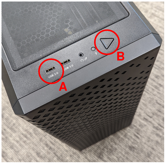
The following two images, with reference labels given in red, are provided to support these instructions:
1. Load the AVA Flasher Image onto a USB Storage Device
First, it is necessary to use the Build Host to load AVA’s bootable ‘Flasher Image’ onto a USB storage device. This will later be connected to the AVA Developer Platform and used to boot the machine. The steps to do this are as follows:
On the Build Host: run the following commands to download and unpack the AVA Flasher Image from ADLINK’s AVA Developer Platform Downloads Page into an appropriate storage directory, here created as
~/ava_flasher_image:mkdir -p ~/ava_flasher_image && cd ~/ava_flasher_image wget https://hq0epm0west0us0storage.blob.core.windows.net/%24web/public/COMe/Ampere/AVA/Images/Yocto/adlink-flasher-image-ava.tar.xz tar -xJf adlink-flasher-image-ava.tar.xz && cd adlink-flasher-image-ava
On the Build Host: connect a USB storage device (minimum size of 64 GB) and identify it using the
lsblkcommand:lsblk
This will output, for example:
NAME   MAJ:MIN RM   SIZE RO TYPE MOUNTPOINT
sdc      8:0    0    64G  0 disk
...
Warning
In this example, the USB storage device is the /dev/sdc device. As this
may vary on different machines, care should be taken when copying and pasting
the following commands.
On the Build Host: prepare for the Flasher Image copy:
sudo umount /dev/sdc*
cd ~/ava_flasher_image
Warning
The next step will result in all prior partitions and data on the USB storage device being erased. Please backup before continuing.
On the Build Host: transfer the Flasher Image onto the USB storage device using the
bmaptoolutility:sudo bmaptool copy --bmap adlink-flasher-image-ava.wic.bmap adlink-flasher-image-ava.wic.gz /dev/sdcSafely eject the USB storage device from the Build Host.
2. Boot AVA into the Flasher Image Loaded on the USB Storage Device
Next, prepare the AVA Developer Platform as follows.
Connect a USB to RS232 female DB9 serial converter cable between the Build Host and the
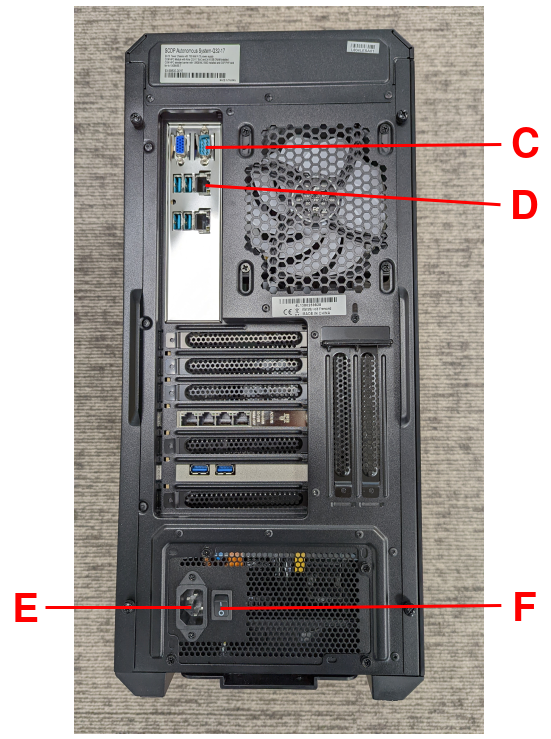
Serial Consoleport on the AVA back-panel, markedCin the reference images.Connect the AVA Developer Platform to the network via the
GbE System (In
Band)
ethernet port, markedDin the reference images.Provide power to the AVA Developer Platform via a C13 mains power cable connected to the
Power Inputport, markedEin the reference images.Switch the AVA Developer Platform’s
Power Main Switchon, markedFin the reference images.Connect the USB storage device containing the AVA Flasher Image to the AVA Developer Platform using a USB 3.0 port, marked
Ain the reference images.
Then, set up the Build Host to access the AVA Developer Platform via a serial console:
On the Build Host: find the TTY USB device in the
/devdirectory that corresponds to the serial connection from the Build Host to the AVA Developer Platform that was set up in step 5, via:ls /dev/ttyUSB*In this example, the corresponding TTY USB device is assumed to be
/dev/ttyUSB0.The port should be configured with the following settings:
115200 Baud
8N1
No hardware or software flow support
On the Build Host: set up a terminal to interface with the AVA Developer Platform’s serial console. This terminal will be referred to as the ‘Serial Console Terminal’. Any terminal applications such as
putty,screenorminicomwill work. Thescreenutility is used in the following command:sudo screen /dev/ttyUSB0 115200
Power-on the AVA Developer Platform via the power button, marked
Bin the reference images.The Serial Console Terminal should then start receiving output from the AVA boot process.
On the Serial Console Terminal: interrupt the boot process to access the boot options menu, by entering
ESCAPEat the prompt (by pressing the ESC key once on the keyboard) shown in the following image:
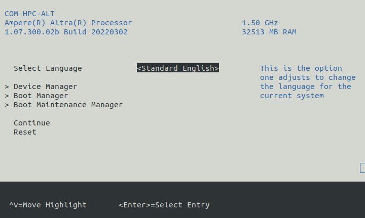
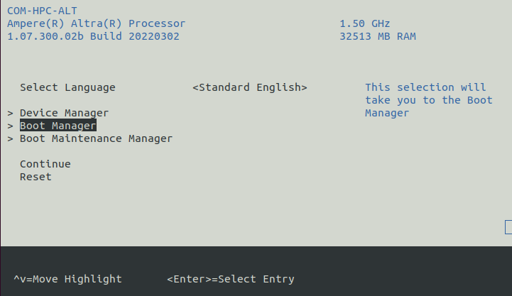
14. On the Serial Console Terminal: move to the Boot Manager entry using
the arrow keys, and select it by pressing the ENTER key:
On the Serial Console Terminal: the connected USB storage device containing the AVA Flasher Image should then be visible in the
Boot
Manager Menu
. Highlight that USB storage device entry using the arrow keys and select it by pressing theENTERkey. An exampleBoot Manager Menushowing a connected USB storage device is shown in the following image: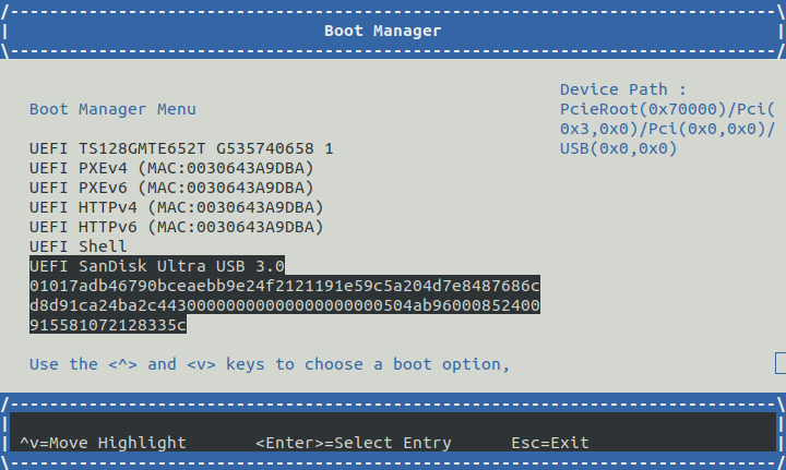
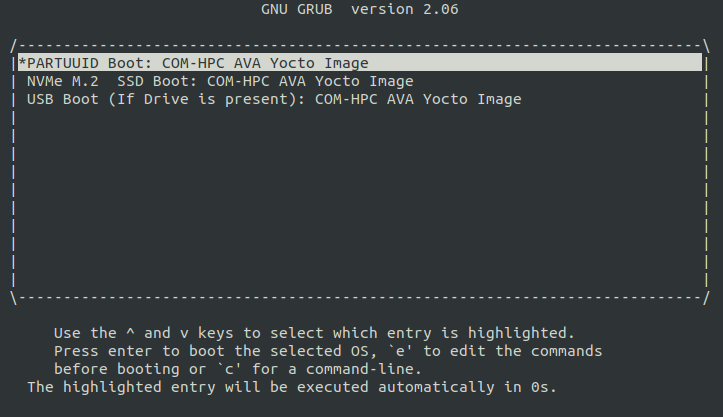
On the Serial Console Terminal: a GRUB2 boot menu will appear as shown in the following image:
Output from the AVA Flasher Image boot process should then appear on the Serial Console Terminal, and this process should result in a Linux console, with no manual account log-in required, such as the following:
Poky (Yocto Project Reference Distro) 4.0.1 ava ttyAMA0

ava login: root (automatic login)

root@ava:~#
3. Flash the EWAOL Distribution Image onto the AVA NVMe M.2 Storage Device
To flash the EWAOL distribution image onto the AVA’s persistent storage, it must first be transferred to the USB storage device which is running the AVA Flasher Image on the AVA Developer Platform. The steps for doing this are as follows:
On the Build Host: create or swap to a different terminal from that used for the Serial Console Terminal, such as the one that was used to execute the
kas buildcommands during the build instructions described previously. This terminal will be referred to as the ‘Build Host Terminal’.On the Build Host Terminal: change the working directory to the directory which contains the Yocto build folder (here assumed to be the root directory of the cloned
meta-ewaolrepository), and prepare for the EWAOL distribution image copy:Baremetal
cd build/tmp_baremetal/deploy/images/ava/Virtualization
cd build/tmp_virtualization/deploy/images/ava/On the Serial Console Terminal: determine the IP address associated with the AVA Flasher Image running on the AVA Developer Platform, by running the following command:
ifconfig eth0 | grep "inet addr"Running this command will output, for example:
inet addr:[IP] Bcast:10.1.195.255 Mask:255.255.254.0The relevant IP address to extract is denoted
[IP]in this example output, which is also used to the reference the IP address in the next step.On the Serial Console Terminal: define an environment variable to hold the IP address and allow copy-pasting of the following commands, by running:
export TARGET_IP=[IP]Be sure to replace
[IP]in this command with the IP address determined in the previous step.On the Build Host Terminal: transfer the EWAOL distribution image to the AVA Developer Platform using the
scputility. The command to run depends on the target EWAOL distribution image:Baremetal distribution image:
scp ewaol-baremetal-image-ava.wic.* root${TARGET_IP}:/tmp/Baremetal-SDK distribution image:
scp ewaol-baremetal-sdk-image-ava.wic.* root@${TARGET_IP}:/tmp/Virtualization distribution image:
scp ewaol-virtualization-image-ava.wic.* root@${TARGET_IP}:/tmp/Virtualization-SDK distribution image:
scp ewaol-virtualization-sdk-image-ava.wic.* root@${TARGET_IP}:/tmp/On the Serial Console Terminal: once the file transfer has completed, flash the EWAOL distribution image to the AVA NVMe M.2 storage device using the
bmaptoolutility.Note
This guidance assumes that the AVA Developer Platform storage drives and partitions have not been modified, and no additional storage devices have been connected other than those described in these instructions. The AVA NVMe M.2 storage device therefore corresponds to the
/dev/nvme0n1device.Warning
The next step will result in all prior partitions and data on the AVA NVMe M.2 storage device to be erased.
Baremetal distribution image:
bmaptool copy --bmap /tmp/ewaol-baremetal-image-ava.wic.bmap /tmp/ewaol-baremetal-image-ava.wic.gz /dev/nvme0n1Baremetal-SDK distribution image:
bmaptool copy --bmap /tmp/ewaol-baremetal-sdk-image-ava.wic.bmap /tmp/ewaol-baremetal-sdk-image-ava.wic.gz /dev/nvme0n1Virtualization distribution image:
bmaptool copy --bmap /tmp/ewaol-virtualization-image-ava.wic.bmap /tmp/ewaol-virtualization-image-ava.wic.gz /dev/nvme0n1Virtualization-SDK distribution image:
bmaptool copy --bmap /tmp/ewaol-virtualization-sdk-image-ava.wic.bmap /tmp/ewaol-virtualization-sdk-image-ava.wic.gz /dev/nvme0n1On the Serial Console Terminal: once the
bmaptoolprocess has complete, power-off the AVA Developer Platform by running:poweroffRemove the USB storage device containing the AVA Flasher Image from the AVA Developer Platform.
Power-on the AVA Developer Platform via the power button, marked
Bin the reference images.
The EWAOL distribution boot process should then be output to the Serial Console Terminal. After the boot process has completed, the EWAOL log-in prompt should appear and the distribution has been successfully deployed.
Run
The EWAOL distribution image can be logged into as ewaol user. See
User Accounts for more information
about user accounts and groups.
On an EWAOL virtualization distribution image, this will access the Control VM.
To log into a Guest VM, the xl tool can be used. For example, on a default
EWAOL virtualization distribution image:
sudo xl console ewaol-guest-vm1
This command will provide a console on the Guest VM, which can be exited by
entering Ctrl+]. See the xl documentation for further details.
The distribution can then be used for deployment and orchestration of application workloads in order to achieve the desired use-cases.
Validate
As an initial validation step, check that the appropriate Systemd services are running successfully, depending on the target architecture:
Baremetal Architecture:
docker.service
k3s.serviceThese services can be checked by running the command:
systemctl status --no-pager --lines=0 docker.service k3s.serviceAnd ensuring the command output lists them as active and running.
Virtualization Architecture:
docker.service
k3s.service
xendomains.serviceThese services can be checked by running the command:
systemctl status --no-pager --lines=0 docker.service k3s.service xendomains.serviceAnd ensuring the command output lists them as active and running.
More thorough run-time validation of EWAOL components are provided as a series
of integration tests, available if the meta-ewaol-config/kas/tests.yml kas
configuration file was included in the image build. These are detailed at
Run-Time Integration Tests.
The integration tests that this command will execute are detailed in Validation, along with the expected format of the test output and additional details for running and customizing the validation.
Reproducing the EWAOL Use-Cases
With the EWAOL distribution running and validated, it can be used to achieve the target EWAOL Use-Cases.
This section briefly demonstrates simplified use-case examples, where detailed instructions for developing, deploying, and orchestrating application workloads are left to the external documentation of the relevant technology, as stated in the Documentation Assumptions.
Note
The following example instructions form similar but simplified versions of the activities carried out by the run-time validation tests that can be included on the EWAOL distribution. See Validation and the test implementations for further demonstrations of EWAOL use-cases.
Deploying Application Workloads via Docker and K3s
This example use-case is performed on the:
Baremetal distribution image
Virtualization distribution image
This example deploys the Nginx webserver as an application workload, using
the nginx container image available from Docker’s default image repository.
The deployment can be achieved either via Docker or via K3s, as follows:
Reboot the image and log-in as the
ewaoluser.On a virtualization distribution image, this will produce a console on the Control VM.
Deploy the example application workload:
Deploy via Docker
2.1. Run the following example command to deploy via Docker:
sudo docker run --name nginx_docker_example -p 8082:80 -d nginx2.2. Confirm the Docker container is running by checking its
STATUSin the container list:sudo docker container listThe container should appear in the list of running containers, with the associated name
nginx_docker_example. For example:CONTAINER ID IMAGE COMMAND CREATED STATUS PORTS NAMES cb7f67053556 nginx "/docker-entrypoint.…" 14 seconds ago Up 13 seconds 0.0.0.0:8082->80/tcp, :::8082->80/tcp nginx_docker_exampleDeploy via K3s
2.1. Run the following example command to deploy via K3s:
cat << EOT > nginx-example.yml && sudo kubectl apply -f nginx-example.yml
apiVersion: v1
kind: Pod
metadata:
  name: k3s-nginx-example
spec:
  containers:
  - name: nginx
    image: nginx
    ports:
    - containerPort: 80
      hostPort: 8082
EOT
2.2. Confirm that the K3s Pod hosting the container is running by checking that its
STATUSisrunning, using:sudo kubectl get pods -o wideThe output should be similar to the following example output, which was captured on the N1SDP:
NAME                READY   STATUS    RESTARTS   AGE   IP          NODE    NOMINATED NODE   READINESS GATES
k3s-nginx-example   1/1     Running   0          28s   [IP]   n1sdp   <none>           <none>
After the Nginx application workload has been successfully deployed, it can be interacted with on the network, via for example:
wget localhost:8082This should download the webserver’s default
index.htmlpage and return a successful exit status, similar to the following example output:--YYYY-MM-DD HH:mm:ss-- http://localhost:8082/ Resolving localhost (localhost)... ::1, 127.0.0.1 Connecting to localhost (localhost)|::1|:8082... connected. HTTP request sent, awaiting response... 200 OK Length: 615 [text/html] Saving to: ‘index.html’ index.html 100%[===========================================================================>] 615 --.-KB/s in 0s YYYY-MM-DD HH:mm:ss (189 MB/s) - ‘index.html’ saved [615/615]
Note
As both methods deploy a webserver listening on port 8082, the two methods cannot be run simultaneously and one deployment must be stopped before the other can start.
To stop the application workload deployed via Docker, use the command:
sudo docker stop nginx_docker_example
The container should then no longer appear in the list of running containers
given by sudo docker container list.
To stop the application workload deployed via K3s, use the command:
sudo kubectl delete pod k3s-nginx-example
The K3s Pod which was running the container should no longer appear in the
list of K3s Pods given by sudo kubectl get pods -o wide.
Orchestrating Resource-Managed and Isolated Application Workloads via K3s and Xen VMs
This example use-case is performed on the:
Virtualization distribution image
This example uses the K3s orchestration framework to use the Control VM to schedule an Nginx webserver application workload for execution on the Guest VM.
To do this, it is first necessary for a K3s agent to be initialized on the Guest VM and connected with the K3s server running on the Control VM, to form a cluster. The application workload can then be scheduled for deployment to the Guest VM via K3s orchestration. This example process is as follows:
Log-in to the Control VM
Reboot the virtualization distribution image, then log-in as the
ewaoluser.
Connect Guest VM K3s Agent
2.1. On the Control VM, determine its IP address via:
ifconfig xenbr02.2. On the Control VM, determine the node-token for the K3s server via:
sudo cat /var/lib/rancher/k3s/server/node-token2.3. On the Control VM, log in to the Guest VM as the
ewaoluser, via:sudo xl console ewaol-guest-vm12.4. On the Guest VM, and denoting the IP address and node-token as
[IP]and[TOKEN]respectively, change theExecStart=line in/lib/systemd/system/k3s-agent.serviceto:ExecStart=/usr/local/bin/k3s agent --server=https://[IP]:6443 --token=[TOKEN] --node-label=ewaol.node-type=guest-vm2.5. On the Guest VM, start the K3s Agent with these values via:
sudo systemctl daemon-reload && sudo systemctl start k3s-agent2.6. On the Guest VM, disconnect from it and return to the Control VM via:
Ctrl+]2.7. On the Control VM, ensure that the K3s server and the Guest VM’s K3s agent are connected, by running:
sudo kubectl get nodesThe hostname of the Guest VM should appear as a node in the list, with a
STATUSofready. The output should be similar to the following example, produced when running this step on the N1SDP:NAME STATUS ROLES AGE VERSION ewaol-guest-vm1 Ready <none> 22s v1.22.6-k3s1 n1sdp Ready control-plane,master 6m40s v1.22.6-k3s1
Schedule Application Workload
3.1. On the Control VM, schedule the Nginx application workload to be deployed on the Guest VM, by running the following example command:
cat << EOT > nginx-example.yml && sudo kubectl apply -f nginx-example.yml
apiVersion: v1
kind: Pod
metadata:
  name: k3s-nginx-example
spec:
  containers:
  - name: nginx
    image: nginx
    ports:
    - containerPort: 80
      hostPort: 8082
  nodeSelector:
    ewaol.node-type: guest-vm
EOT
3.2. On the Control VM, confirm that the K3s Pod (which hosts the container) was deployed to the Guest VM by checking its
STATUSisrunningand itsNODEis the Guest VM’s hostname, by running the following command:sudo kubectl get pods -o wideThe output should be similar to the following example output:
NAME                READY   STATUS    RESTARTS   AGE   IP          NODE              NOMINATED NODE   READINESS GATES
k3s-nginx-example   1/1     Running   0          33s   [IP]   ewaol-guest-vm1   <none>           <none>
Access the Application Workload
The webserver will then be running on the Guest VM. To access the webserver:
4.1. On the Control VM, log in to the Guest VM as the
ewaoluser, via:sudo xl console ewaol-guest-vm14.2. On the Guest VM, access the webserver by running the following example command:
wget localhost:8082This should download the webserver’s default
index.htmlpage and return a successful exit status, similar to the following example output:--YYYY-MM-DD HH:mm:ss-- http://localhost:8082/ Resolving localhost (localhost)... ::1, 127.0.0.1 Connecting to localhost (localhost)|::1|:8082... connected. HTTP request sent, awaiting response... 200 OK Length: 615 [text/html] Saving to: ‘index.html’ index.html 100%[===========================================================================>] 615 --.-KB/s in 0s YYYY-MM-DD HH:mm:ss (189 MB/s) - ‘index.html’ saved [615/615]
While the Guest VM is running this application workload, other deployments may be carried out (for example) on the Control VM, thus enabling isolation between application workloads running on resource-managed virtualized hardware.